| Fiber Optics 101 — The Basics | |||||
|
Source: David R. Goff. Fiber Optic Video Transmission, 1st ed. Focal Press: Woburn, Massachusetts, 2003 and other private writings. |
|||||
|
Optical Fiber
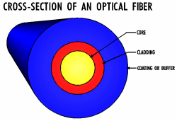
Optical fibers are extremely thin strands of ultra-pure glass designed to transmit light from a transmitter to a receiver. These light signals represent electrical signals that include video, audio, or data information in any combination. Figure 1 shows the general cross-section of an optical fiber. The fiber consists of three main regions. The center of the fiber is the core. This region actually carries the light. It ranges in diameter from 9 microns (μm) to 100 microns in the most commonly used fibers. Surrounding the core is a region called the cladding. This part of the fiber confines the light in the core. The cladding typically has a diameter of 125 microns or 140 microns. A key design feature of all optical fibers is that the refractive index of the core is higher than the refractive index of the cladding. Both the core and cladding are usually doped glass materials. Other fiber types incorporate quartz or pure fused silica and plastic, but these are not used in mainstream high-performance applications. The outer region of the optical fiber is called the coating or buffer. The buffer, typically a plastic material, provides protection and preserves the strength of the glass fiber. Typical diameters for the buffer are 250 microns, 500 microns, and 900 microns. |
Figure 1 - Cross-Section of a Typical Optical Fiber
|
||||
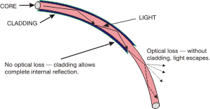
| The development of glass-coated glass fibers was motivated by the optical loss experienced when using uncoated glass fibers. The inner fiber, or core, was used to transmit the light, while the glass coating, or cladding, prevented the light from leaking out of the core by reflecting the light within the boundaries of the core. The cladding is designed so that it causes the light to be angled back into the core as illustrated in Figure 2 and thus carried along the length of the fiber. |
Figure 2 - Light Guided Along a Bent Optical Fiber by Total Internal Reflection |
||||
|
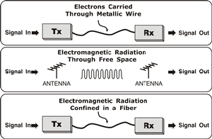
Why is fiber important? Because it provides a private pipeline that can carry huge amounts of data. Alternatives are over-the-air broadcast or hard-wired copper wires carrying electrons. Figure 3 demonstrates the three basic schemes that can be used for transmitting (or sending) information from one point to another.
|
Figure 3 - Three Basic Schemes for Sending Information from One Point to Another
|
||||
|
In the growing world of improved communication, fiber optics offers a method of transmitting information (or data) that allows for clearer, faster, more efficient communications than copper. A fiber optic transmission system (FOTS) holds many advantages over a copper wire system. For example, while a simple two-strand wire can carry a low-speed signal over a long distance, it cannot send high-speed signals very far. Coaxial cables can better handle high-speed signals but still only over a relatively short distance.
|
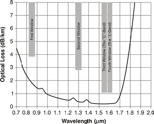
Figure 4 - Near-Infrared Wavelengths Used for Fiber Optic Communications
|
||||
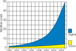
| In the late 1990's, the telecommunications industry (e.g. the phone company) faced tremendous challenges due to the ever growing amounts of data being generated by the rapidly expanding Internet. In the late 90's, the total load generated by Internet traffic matched and then exceeded the load generated by voice calls. Today the load from Internet traffic is five to ten times as large as the load generated by voice calls. The dominance of the load generated by Internet over voice is shown in Figure 5. |
Figure 5 - Voice & Data Growth |
||||
|
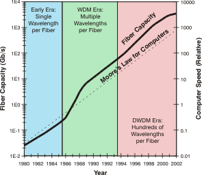
Fiber optics offered the only practical means of meeting this soaring demand. The telecommunications industry already had a great deal of fiber in the ground, but most of it was already being used and the cost and time to lay additional fiber was prohibitive in many cases. The telecommunications industry needed a new solution that would allow them to economically keep up with demand. The companies that could provide these new solutions could be assured of a very large amount of business providing upgraded systems. The capacity of commercial optical fiber communications systems has increased about as fast as Moore’s Law for integrated circuits, doubling every two years, as shown in Fig. 6. The recent rate of increase for experimental systems has been even faster. |
Figure 6 - Capacity of Optical Fiber Over Time |
||||
|
Three problems needed to be addressed by the next generation of fiber
optic transport systems (FOTS) for the telecommunications industry.
First, the data rate had to be increased. In the mid to late 1990's, the
fastest data rate being used commercially was 2.5 Gb/s, also referred to
as OC-48. This needed to be increased to handle the increasing need. The
usual speed increase for SONET was a factor of four, so the next logical
data rate was 10 Gb/s or OC-192. Second, it was highly desirable to put
more than one channel of information onto a single fiber. This would
reduce or eliminate the need to deploy more fiber. Third, the maximum
distance that a FOTS could serve needed to increase dramatically. This
would reduce the overall cost of the data transmission link by
eliminating or reducing the need for costly signal regeneration
facilities along the length of the transmission path. The gap between the unfilled growing needs of the telecommunications industry and the growing demands for more bandwidth created a huge opportunity for fiber optics to make a breakthrough in performance and cost. Several pieces of new fiber optic technology including DWDM (Dense Wavelength Division Multiplexing), EDFA’s (Erbium-Doped Fiber Amplifiers), Solitons, Dispersion Compensators, FEC coding and many more were rushed out of the hands of researchers and rapidly converted into next-generation FOTS that provided more than 100 times the capacity on one fiber compared to existing hardware and at the same time substantially increased the maximum allowable transmission distances.
|
|||||
| Return to Top of Page | |||||
|
|||||

