| Wideband EDFA | |||||
|
Source: David R. Goff. Fiber Optic Video Transmission, 1st ed. Focal Press: Woburn, Massachusetts, 2003 and other private writings. |
|||||
|
Technology Basics
Erbium-Doped Fiber Amplifiers (EDFA’s) are one of the fundamental breakthroughs that allowed long-haul DWDM systems to flourish. Before EDFA’s were developed, an electronic repeater was required at intermediate points about 100 km apart. The repeater is essentially a fiber optic receiver connected directly to a fiber optic transmitter. EDFA’s allow optical signals to be transmitted over longer distances without the need for conventional repeaters. At the heart of the EDFA, the fiber is doped with erbium, a rare earth element that happens to have the appropriate energy levels in its atomic structure for amplifying light at 1550 nm. A 980 nm or 1480 nm "pump" laser is used to inject energy into the erbium-doped fiber. When a weak signal at 1550 nm enters the fiber, the light stimulates the erbium atoms to release their stored energy as additional 1550 nm light. This process continues as the signal passes down the fiber, growing stronger and stronger as it goes. |
|||||
|
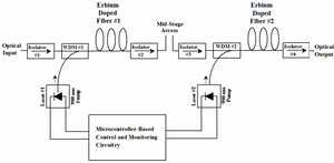
Figure 1 shows a two-stage EDFA with Mid-Stage Access. In this case, two simple single-stage EDFA’s are packaged together. The output of the first stage EDFA and the input of the second stage EDFA are brought out to the user. This is called mid-stage access. Mid-stage access is important in very high performance fiber optic systems. These systems often require the periodic use of elements such as dispersion compensating fiber (DCF) in order to reduce the overall dispersion. The problem with DCF is that its insertion loss is quite high, 10 dB or more. If the DCF is placed at the mid-stage access point of the two-stage EDFA, it has very little detrimental effect on the system. The user still realizes significant gain through the EDFA, even though a high optical loss piece of DCF has been added. |
Figure 1 - Dual-Pump EDFA with Mid-Stage Access
|
||||
| A typical EDFA operates as follows; The optical input first passes through optical isolator, Isolator #1. An optical isolator is a device that only allows light to pass from left to right. Next the light passes through WDM#1. WDM#1 provide a means of injecting the 980 nm pump wavelength into the first length of erbium-doped fiber. WDM#1 also allows the optical input signal to be coupled into the erbium-doped fiber with minimal optical loss. The erbium-doped optical fiber is usually tens of meter long. The 980 nm energy pumps the erbium atoms into an excited state that decays slowly. When light in the 1550 nm band travels through the erbium-doped fiber it causes stimulated emission of radiation, much like in a laser. In this way, the 1550 nm optical input signal gains strength. The output of the erbium-doped fiber then goes through optical isolator, Isolator#2. The output of Isolator#2 is made available to the user. Typically some sort of dispersion compensating device will be connected at the mid-stage access point. The light then travels through Isolator#3 and the WDM#2. WDM#2 couples additional 980 nm energy from a second pump laser into the other end of a second length of erbium-doped fiber, increasing gain and output power. Finally, the light travels through Isolator#4. |
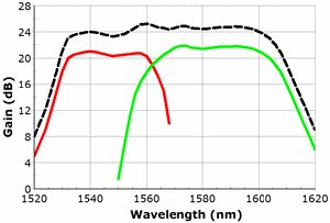
Figure 2 - Optical Gain Spectrum of a Hybrid Optical Amplifier
|
||||
| The beauty of the EDFA, is that all the amplification is done with photons, i.e. the signal does not need to be converted to an electrical signal to be amplified. The incoming optical signal is boosted optically and almost all active components are avoided. The output power from an EDFA can be quite large and fewer amplifiers may be needed in a given system design. The amplification process is independent of the data rate. This is a very powerful benefit, because upgrading a system means only changing the launch/receive terminals. EDFA’s that would already be in place will work fine for future data rate upgrades. An EDFA may also be used in a dense wavelength-division multiplexing (DWDM) system in which the system is upgraded by adding additional sources at different wavelengths and combining them onto a single fiber using a DWDM multiplexer. | |||||
|
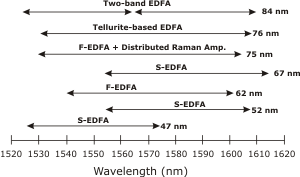
The most basic EDFA design is only useful for amplifying light over a fairly narrow, 12 nm wide band. By adding some gain equalization filters, this can be easily increased to 25 nm or more. There are more exotic doped fibers that increase the useful amplification band to 40 nm. For the highest performance optical communication systems, which may be carrying 100 or more optical wavelengths, it may be necessary to increase the bandwidth of the optical amplifier to nearly 80 nm. This us usually accomplished by some sort of hybrid optical amplifier, consisting of two separate optical amplifiers, one for the lower 40 nm band and the second for the upper 40 nm band. Figure 2 shows the optical gain spectrum of such a hybrid optical amplifier. The response of the individual gain sections is shown. Figure 3 shows various optical amplifier topologies and the bandwidth performance level that they can achieve. |
Figure 3 - Wideband EDFA/Raman Amplifier Examples
|
||||
| Return to Top of Page | |||||
|
|||||


