| Raman Amplifier | |||||
|
Source: David R. Goff. Fiber Optic Video Transmission, 1st ed. Focal Press: Woburn, Massachusetts, 2003 and other private writings. |
|||||
|
Technology Basics
The Raman optical amplifier is based on an entirely different principle than EDFA’s or conventional lasers. In EDFA’s and conventional lasers, atoms are pumped to a high energy state and then drop to a lower state, releasing their energy, when a suitable wavelength photon passes nearby. Raman optical amplifiers utilize Raman scattering (the Raman effect, often called SRS - Stimulated Raman Scattering) to create optical gain. Initially SRS was considered to be a detriment to high channel count DWDM systems. In these systems, as light traveled down the fiber, energy would be "robbed" from the shorter wavelength channels, boosting the amplitude of the longer wavelength channels.
Figure 1 shows the typical transmit spectrum or a six-channel DWDM system. Note that all of the six wavelengths have identical amplitudes. These signals are all in the 1550 nm window. |
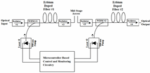
Figure 1 - Dual-Pump EDFA with Mid-Stage Access
|
||||
| Now refer to Figure 2. Several things can be noticed to be different. First, the noise background is a bit higher. The main change is that the amplitudes of the six wavelengths are now very different. The lower wavelengths now have smaller amplitude than the upper wavelengths. This is because the SRS effect has robbed energy from the lower wavelengths and fed that energy to the upper wavelengths. |
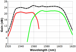
Figure 2 - Optical Gain Spectrum of a Hybrid Optical Amplifier
|
||||
| A Raman optical amplifier is not a "black box" like an EDFA. It consists of little more than a high-power pump laser, usually called a Raman laser, and a WDM or directional coupler. The optical amplification occurs in the transmission fiber itself. The optical amplification is distributed along the transmission line. Optical signals are amplified up to 10 dB in the network optical-fiber. The Raman optical amplifiers have wide gain bandwidth (up to 100 nm). They can use any installed transmission optical-fiber (single-mode optical fiber, TrueWave, etc.). In effect, they reduce the effective span loss and improve noise performance of the transmission line by boosting the optical signal in transit. They can be combined with erbium-doped fiber amplifiers (EDFA) to achieve very wide optical gain flattened bandwidth. Figure 3 shows the topology of a typical Raman optical amplifier. The two key elements of the Raman optical amplifier are the pump laser and the directional coupler. The pump laser, in this case, has a wavelength of 1535 nm. The circulator provides a convenient means of injecting light backwards in to the transmission path with minimal optical loss. |
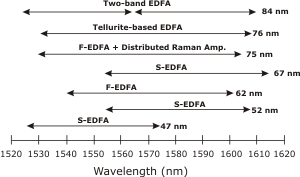
Figure 3 - Wideband EDFA/Raman Amplifier Examples
|
||||
| Return to Top of Page | |||||
|
|||||


