| Fiber Optics Communications | |||||||||||||||||||||
|
Source: David R. Goff. Fiber Optic Video Transmission, 1st ed. Focal Press: Woburn, Massachusetts, 2003 and other private writings. |
|||||||||||||||||||||
|
Typical Fiber Optic Communication Systems
Modern fiber optic data transmission systems can be extraordinarily complex as the data rates are increased along with a large number of channels over very long distances. In order to understand how a fiber optic data transmission system operates, let’s first look at the most basic possible example. Let’s first review some basic fiber optic terminology.
|
Figure 1 - Electromagnetic Spectrum |
||||||||||||||||||||
|
The term wavelength refers to the wavelike property of light, a characteristic shared by all forms of electromagnetic radiation. Wavelength is the measurement of the distance a single cycle of an electromagnetic wave covers as it travels through a complete cycle. Wavelengths for fiber optics are measured in nanometers (the prefix nano meaning one-billionth) or microns (the prefix micro meaning one-millionth). Wavelengths of light used in fiber optic applications can be broken into two main categories: near-infrared and visible. Visible light, as defined by the human eye, ranges in wavelengths from 400 to 700 nanometers (nm) or 0.4 μm or 400 nm to 0.7 μm or 700 nm and has very limited uses in fiber optic applications, due to the high optical loss. Near-infrared wavelengths range from 700 to 1,700 nanometers; these wavelengths are almost always used in modern fiber optic systems.
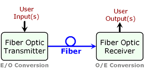
The system shown in Figure 2 is, of course, a very simple example that is no longer representative of modern fiber optic transmission systems. |
Figure 2 - Basic Elements of a Fiber Optic Transmission System |
||||||||||||||||||||
| The next level of complexity that was added to fiber optic transmission systems was the addition of multiple wavelengths of light on each fiber. Each wavelength of light is a distinct "color" that can be separated out at the receiver end by using various optical filters. This technique is referred to as WDM (Wavelength Division Multiplexing). Figure 3 shows a basic WDM system with two wavelengths being transmitted in the same direction on the fiber. The first WDM systems that were deployed used wavelengths of 1310 nm and 1550 nm for λ1 and λ2. WDM systems were popular upgrades in the telecommunications industry in the late 1980's and early 1990's. They allowed the information carrying capacity of each fiber to be doubled. |
Figure 3 - Basic WDM Fiber Optic Transmission System |
||||||||||||||||||||
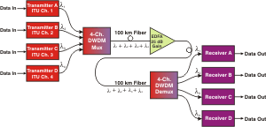
| As the load from Internet traffic increased, WDM systems evolved into systems that could carry a multitude of wavelengths (colors). These systems were called DWDM (Dense Wavelength Division Multiplexing) systems. A key development that made DWDM systems practical was the EDFA (Erbium-Doped Fiber Amplifier). The EDFA allowed the multitude of wavelengths on the fiber to boosted simultaneously making the systems very economical. Early systems carried four to eight wavelengths and then sixteen. The increase in capacity per fiber was dramatic, but was still insufficient to handle the exponentially growing Internet traffic load. A typical small DWDM system configuration is shown in Figure 4. |
Figure 4 - Basic 4-Channel DWDM Fiber Optic Transmission System |
||||||||||||||||||||
| Modern DWDM systems incorporate a number of sophisticated elements that allow the channel count and distances to be very large. Some common elements that are incorporated into today's DWDM systems are: | |||||||||||||||||||||
|
|||||||||||||||||||||
| Return to Top of Page | |||||||||||||||||||||
|
|||||||||||||||||||||


