| Forward Error Correction (FEC) | |||||
|
Source: David R. Goff. Fiber Optic Video Transmission, 1st ed. Focal Press: Woburn, Massachusetts, 2003 and other private writings. |
|||||
|
Technology Basics
Error correcting codes are considerable more complex than error detecting codes and are ubiquitous in nearly every modern communication application. Error correcting codes even find widespread use in CD and DVD players. In order to present an example of an error correcting code, we need to introduce and define two terms; binary and parity. In the prior examples of error detecting codes, we used numbers like 7, 3, 8, etc. These are base ten numbers, the counting systems familiar to us in everyday life. Binary numbers are base two numbers. They can only have two possible values, 0 or 1. Binary is the system used in nearly all communication and computer systems. The second concept that we need to understand, is a concept called parity. Parity is a term that is used in binary communication systems to indicate whether the numbers of 1's in a transmission is even or odd. If the number of 1's is an even number, then parity is said to be even and conversely for odd parity. |
|||||
|
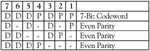
The Hamming Code Consider a message having four data bits (D) which is to be transmitted as a 7-bit codeword by adding three error control bits. This would be called a (7, 4) code. That means that the total codeword length is seven bits, but only four of those bits are actually data. The three bits to be added are three EVEN Parity bits (P), where the parity of each is computed on different subsets of the message bits as shown in Figure 1.
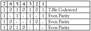
For example, the message 1011 would be sent as 1010101 as demonstrated in Figure 2. |
Figure 1 - EVEN Parity Algorithm
Figure 2 - Sample Message Computation
|
||||
|
It may now be observed that if an error occurs in any of the seven bits, that error will affect different combinations of the three parity bits depending on the bit position.
Message
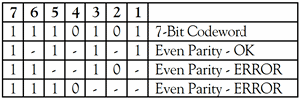
Message The above error can be corrected by examining which of the three parity bits was affected by the bad bit as shown in Figure 3.
The pattern of the parity bit errors indicates which bit in the codeword is in error, thus it can be corrected. |
Figure 3 - Return to Zero (RZ) Format
|
||||
|
The value of the Hamming code can be summarized:
The ability to correct single bit errors comes at a cost which is less than sending the entire message twice. (Recall that simply sending a message twice accomplishes no error correction.) As the size of the codeword becomes very large, the extra burden of the error correcting bits becomes negligible. For instance, one possible Hamming code considered for fiber optic submarine transmission is the (18880, 18865) code. That means that the 18,880 bit codeword contains 18,865 actual data bits and 15 error correction bits. More robust forms of FEC may include many more error correction bits so that multiple bit errors can be detected and corrected in each codeword. |
|||||
|
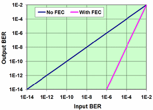
FEC on fiber optics uses a method similar to the Hamming code error correction given above. Typically, for an OC-192 system, there is roughly a 7% overhead added by the FEC process. The base data rate of 10 Gb/s is increased to about 10.7 Gb/s. So for every 1,000 bits of data transmitted, an additional 70 bits of FEC are sent along to allow verification of the integrity of the received data and to correct many of the errors that can occur during transmission over the optical fiber. Figure 4 shows the effect of FEC on the system BER (Bit error Rate). BER is a measure of what fraction of the received bits have errors. A BER of 10-3 means that one out of every 1,000 bits is incorrect. The solid curve shows the result if a given system does not have FEC. The input BER is a measure of errors that occur in the transmission channel. Since, the system lacks FEC, any errors that occur during transmission appear at the system output. The dotted line shows what might happen if an FEC is added to the system. Whereas before an input BER of 10-6 would yield an output BER of 10-6, with FEC it now yields an output BER of 10-14, a very substantial improvement. Adding FEC to the system allows the designer to push distances and data rates farther than might be possible with any other technique or it would allow a system to have more operating margin. |
Figure 4 - Impact of FEC |
||||
| Return to Top of Page | |||||
|
|||||


