| Chromatic Dispersion Compensation | ||||||||||
|
Source: David R. Goff. Fiber Optic Video Transmission, 1st ed. Focal Press: Woburn, Massachusetts, 2003 and other private writings. |
||||||||||
|
Dispersion is a phenomenon that occurs in all types of optical fiber. After attenuation, dispersion is the next limiting factor that determines how much and how far information can be transmitted on a given fiber. There are two main dispersion phenomena that need to be taken into account when designing DWDM systems in single mode fibers: chromatic dispersion and Polarization Mode Dispersion (PMD). In this article, we will focus on chromatic dispersion.
Another property of silica fibers is that the difference
between the speed at which two wavelengths travel varies with the
wavelength range where they are situated. This is best understood in
terms of a dispersion curve. All fibers have a wavelength at which
chromatic dispersion is practically zero. This is referred to as the
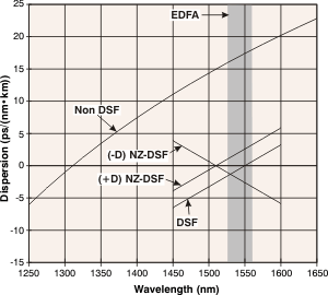
fiber zero dispersion wavelength, or λ0 (see
Figure 1). Two co-propagating wavelength
channels that are in close proximity to λ0 will have a
smaller speed difference than two co-propagating wavelength channels,
with the same spacing, but that are further from λ0. Thus to
accurately assess the degree of dispersion that affects a wavelength
channel - which is comprised of many "wavelengths of light" centered
about its primary wavelength - its position with respect to λ0
must be
considered. Also, as shown in Figure 1,
transmitters with a center wavelength greater than λ0 will
see positive (or anomalous) dispersion; transmitters with a center
wavelength less than λ0 will experience negative (or normal)
dispersion. An optical channel or pulse subjected to positive dispersion
will see its longer wavelength components travel slower than its shorter
counterparts, whereas an optical channel subjected to negative
dispersion will see its longer wavelength components travel faster than
its shorter counterparts. |
Figure 1 - Dispersion of Common Types of Single-Mode Fiber
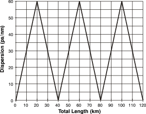
Figure 2 - Dispersion in a Compensated NZ-DSF Fiber Path |
|||||||||
|
This last property is important, as a light pulse that
has undergone a certain amount of negative dispersion can essentially
correct itself by traveling through a medium that has an equivalent
amount of positive dispersion. This is the function that dispersion
compensating modules perform in optical links by introducing, in-line,
an opposite dispersion medium to that of the fiber. Dispersion management refers to the process of designing the fiber and compensating elements in the transmission path to keep the total dispersion to a small number. Typically, dispersion compensating elements are placed every 100 km or so. Figure 2 shows the performance of a fiber path that has alternating lengths of (+D) NZ-DSF and (-d) NZ-DSF every 20 km. The first 20 km length of fiber is (+D) NZ-DSF, so the dispersion increases over that length to 60 ps/nm. The next 20 km length of fiber is (-D) NZ-DSF type, so the dispersion gradually decreases back to zero. This pattern repeats two more times. At the end of the 120 km fiber path, the dispersion has returned to near zero. |
||||||||||
|
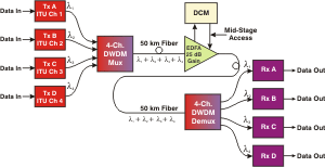
The reality in most applications is that the fiber is already in place and odds are that the fiber is NDSF type. More than 80% of all single-mode fiber worldwide is NDSF type. In these cases, a more common means of controlling dispersion is the use of DCM (Dispersion Compensating Modules) placed at periodic intervals. DCM's are usually one of two types. The first type is DCF or Dispersion Compensating Fiber. This is simply a spool of a special type of fiber that has very large negative dispersion. Typically DCF dispersion can be in the range of -80 ps/(nm∙km), so a 20 km length of DCF can compensate for the dispersion in a 100 km length of NDSF. The second type of DCM is a FBG (Fiber Bragg Grating) type. Here, a series of FBG's or one very long FBG is written into a tens of meter length of fiber to perform the dispersion compensation. Both of these types of DCM's have relatively high insertion loss. A 60 km compensator may exhibit 6 dB of loss or more. Because of this, DCM's are usually co-located with EDFA's. Often they are used with a special type of EDFA that has mid-stage access. This type of EDFA has two gain states. The DCM is placed between the gain stages so that the effect of the large insertion loss of the DCM has no significant impact on the system performance. |
Figure 3 - DCM with Mid-Stage Access EDFA
|
|||||||||
|
Both solutions offer similar performance and cost. There are some differences that can have an impact. The key advantages and disadvantages are shown in the table below. |
||||||||||
|
||||||||||
| Return to Top of Page | ||||||||||
|
||||||||||


