| Fiber Bragg Gratings | |||||
|
Source: David R. Goff. Fiber Optic Video Transmission, 1st ed. Focal Press: Woburn, Massachusetts, 2003 and other private writings. |
|||||
|
Technology Basics
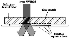
In-fiber Bragg gratings are simple reflecting elements "written" into the core of optical fibers. The process is shown in Figure 1. This is usually accomplished by treating the fiber so that it becomes photosensitive (by loading it with Hydrogen in this case) and then exposing the fiber to UV light through a grating. This introduces periodic variations in the refractive index of the fiber and forms a wavelength-dependent reflection. As light waves interact with the variations in the refractive index, interference effects occur which cause certain wavelengths to reflect more than others.
The size and spacing of the reflective elements allows an almost infinite number of filter responses to be created. Consequently, it has become possible to design a variety of devices based in Fiber Bragg Gratings which offer unique solutions, especially in WDM applications. Bragg gratings are essentially narrow-band devices but can be made broad-band by a variety of means, e.g. by incorporating chirp (non-uniform spacing of the reflecting elements.) Functionality can be increased easily, with sub-dB insertion loss, by combining various types of fiber gratings, narrow or broad bandwidth, with or without designed chirp, along with other optical components.
|
Figure 1 - Making a Bragg Grating
|
||||
| Figure 1 shows a fiber carrying two wavelengths, λ1 and λ2. In this case, λ2 is ahead of λ1 due to dispersion in the fiber that causes λ1 to travel slower than λ2. As the two pulses reach the circulator, it enters port 1 and exits port 2. Both λ1 and λ2 pulses travel vertically in the fiber Bragg grating. At about the middle of the length, λ1 encounters a region of disturbances of refractive index that causes it to reflect and travel back down the grating. Wavelength λ2 travels further up the grating before it reflects. When both λ1 and λ2 pulses reach the circulator, they enter port 2 and are directed to port 3. Since λ2 had to travel farther than λ1, the time spacing between the two pulses is reduced. It could, in fact, be adjusted so that the output pulses overlapped. This is the basic principle used to compensate for chromatic dispersion in long-haul fiber optic transmission systems. |
Figure 2 - Fiber Bragg Grating Used to Compensate for Chromatic Dispersion |
||||
| Return to Top of Page | |||||
|
|||||